
 Current Location: HOME /Knowledge /Vertical Sump Pump
 Date:2024/10/22 0:41:10
 Clicks:
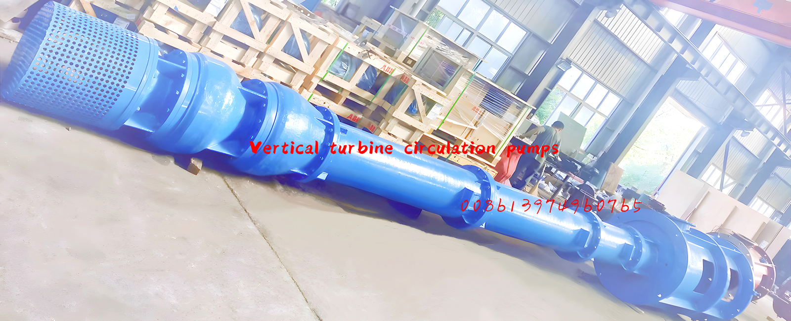
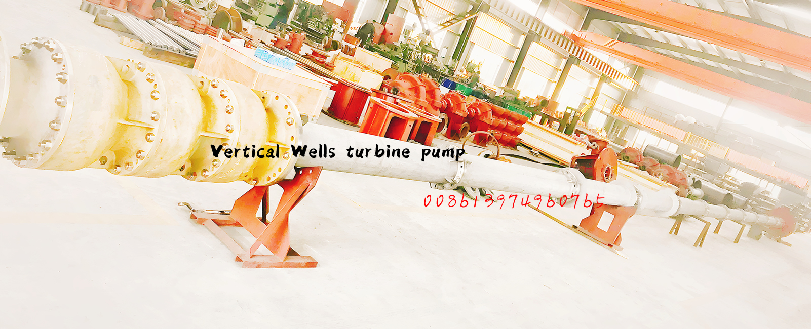
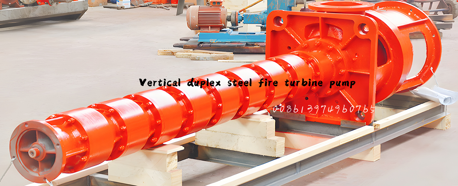
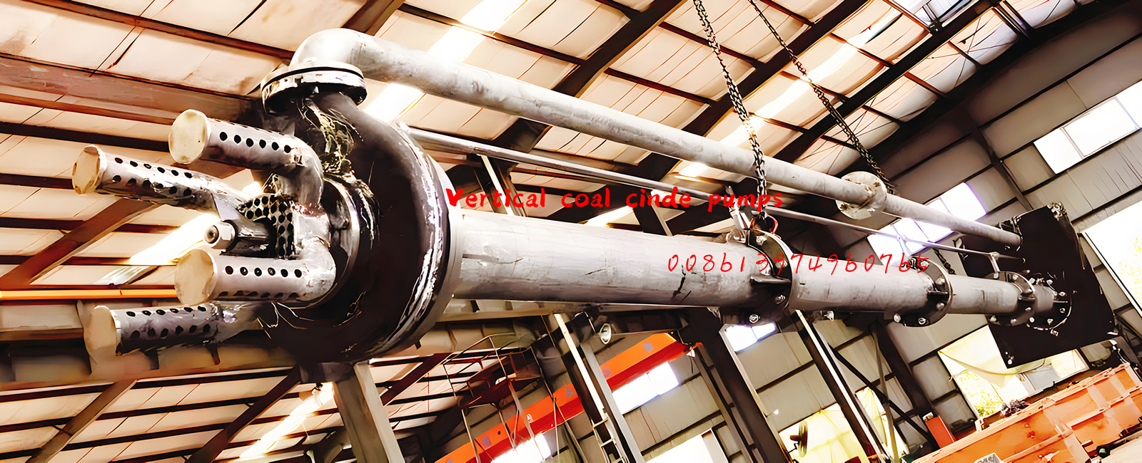
 A combined vertical suspended semi submersible sump pump
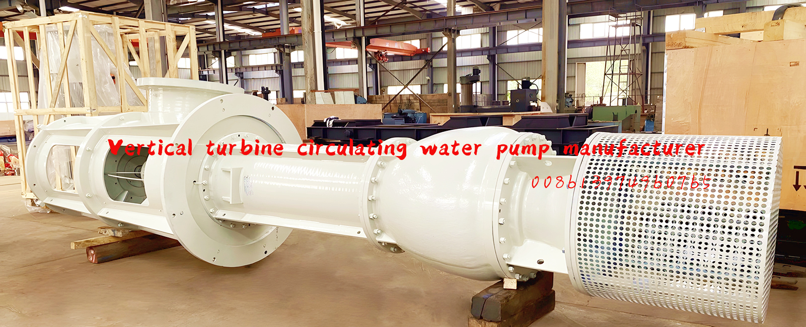
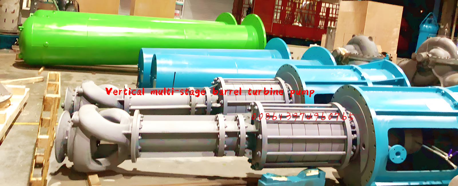
The combined vertical suspended semi submersible sump pump includes an inlet section, radial guide vanes, middle section, space guide vanes, middle protective pipe, lower protective pipe, etc. The inlet section, radial guide vanes, middle section, and space guide vanes are combined and connected and compressed by tightening bolts to form a combined pump chamber. The lower protective pipe and lower connecting pipe are respectively connected and compressed by bolts after being matched with the space guide vanes and lower bearing seats. The middle protective pipe, middle connecting pipe, and middle bearing seat are connected and compressed by bolts after being matched with each other. The pump support is connected and compressed by bolts after being matched with the upper bearing seat and upper connecting pipe to form an independent outlet chamber flow channel; The conduit is equipped with leakage collection devices, monitoring and detection systems, automatic drainage systems, and axial force automatic balancing systems for various detection and control wires. After passing through the conduit, all detection and control wires are connected to the PLC programmable controller in the water pump control room. This technology is ingeniously designed, reduces manufacturing and installation maintenance costs, has a long lift, and has good performance.

Technical requirements: 1. A combined vertical suspended semi submersible sump pump, comprising an inlet section, a radial guide vane, a middle section, a space guide vane, a middle protective pipe, a lower protective pipe, a lower connecting pipe, a middle connecting pipe, an upper connecting pipe, a conduit, a lower bearing cover, an intermediate motor coupling, a pressure reducing sleeve, a liquid throwing cover, a leakage detection probe, a suction pipe I, a suction pipe II, an inlet pipe, a vertical long axis semi submersible sump pump, a submersible solenoid valve, a submersible electric valve, a submersible air pressure detector, a submersible pressure detector, and a pump shaft, characterized in that: the inlet section (2), the radial guide vane (5), the middle section (6), and the space guide vane (8) are combined, and Connected and tightened by tightening bolts (7) to form a combined pump chamber, which is equipped with an impeller (4) and a final stage impeller (29); The pressure reducing sleeve (28) is equipped with a toothed pressure reducing groove (96); The inlet section (2) is provided with two water pipe installation holes (103); The pump shaft (27) is equipped with a liquid throwing cover (40); The water leakage detection probe (107) is installed and fixed on the installation hole (106) of the water leakage detection probe set on the spatial guide vane; The suction pipe I (34) is connected to the suction elbow (104), and the suction pipe I is fixed on the suction pipe installation hole (83) set in the lower bearing seat (13) and inserted into the leakage collection device (26); The suction pipe II (39) is inserted into the storage chamber through the suction pipe installation hole provided on the storage chamber, fixed on the suction pipe installation hole of the storage chamber, and connected and fixed on the suction pipe installation hole provided on the lower bearing seat, so that the leakage collection device and the storage chamber are connected to each other; The inlet pipe (52) is inserted into the storage chamber (75) through the inlet pipe installation hole (68) provided on the storage chamber (75) and fixed on the inlet pipe installation hole of the storage chamber. A submersible solenoid valve (50) is installed on the inlet pipe exposed outside the storage chamber; The pressure reducing sleeve (28) is assembled with the space guide vane (8) to form a pressure reducing chamber, and a pressure reducing pipe is installed on the pressure reducing hole (64) on the space guide vane. The pressure reducing pipe is connected to the water pipe installation hole (103) on the inlet section to form the axial force balance pipe (60) of the water pump; Install two submersible pressure detectors (55, 62) on the axial force balance pipe of the water pump, and install one submersible electric valve (57) in the middle of the two submersible pressure detectors. The wires of the two submersible pressure detectors and the submersible electric valve are connected to the PLC programmable controller in the water pump control room through the conduit (19), forming an automatic axial force balance system for the water pump; The submersible pressure detector (51) is installed on the storage chamber (75) for detecting the pressure inside the storage chamber (75); The middle protective tube (18), the intermediate connecting pipe (17), and the middle bearing seat (15) are connected and compressed with bolts after being matched. The pump support (20) is connected and compressed with bolts after being matched with the upper bearing seat (21) and the upper connecting pipe (117), forming an independent outlet chamber flow channel; The conduit (19) is equipped with various detection and control wires including a leakage collection device (26), a monitoring and detection system (126), an automatic drainage system (128), and an axial force automatic balancing system (125). After passing through the conduit, all detection and control wires are connected to the PLC programmable controller in the water pump control room; The lower connecting pipe (12) is equipped with a liquid storage chamber (75); The vertical long axis semi submersible sump pump (38) is installed at the installation position (66) of the vertical long axis semi submersible sump pump set on the storage chamber (75). The inlet pipe of the vertical long axis semi submersible sump pump (38) is connected to the installation hole (65) of the discharge pipe set on the storage chamber. The discharge pipe of the vertical long axis semi submersible sump pump is connected to the installation hole of the water pipe set on the inlet section (2). A submersible solenoid valve is installed on the discharge pipe of the vertical long axis semi submersible sump pump; A filter screen (105) is installed at the end of the inlet pipe behind the submersible solenoid valve; The probe tube (73) is equipped with an exhaust hole (70), and two submersible water level detection probes (72, 74) are installed inside the probe tube. The probe tube is installed and fixed on the probe tube installation hole (69) set in the storage chamber; The lower protective tube (35) is fitted into the pump shaft (27) and coordinated with the space guide vane (8), and the lower connecting pipe (12) is fitted into the lower protective tube (35) and coordinated with the space guide vane (8), and then connected and fixed with bolts; Insert the lower bearing seat (13) into the pump shaft (27), and insert the suction pipe I (34) fixed on the suction elbow (104) into the suction pipe installation positioning hole (77) on the water separating pipe (78) set on the lower bearing cover (76). The lower bearing seat (13) is matched with the lower protective pipe (35) and the lower connecting pipe (12), and connected and fixed to the installation positioning hole (86) set on the lower bearing seat (13) through the positioning hole (100) set on the lower connecting pipe (12) with bolts (41), forming a leakage collection device (26).

Scan and add WeChat
TEL:
008618507312158 Xiangyin Industrial Park, Jinlong Town, Xiangyin County, Hunan Province, China
  susie@hnljpump.com
 Hotline:
008618507312158
008613974960765